빵판에서 +- 는 아래로 쭉 같은거고
그 사이에는 A-E F-J 각각이 연결된거!

서버 :nputt or http
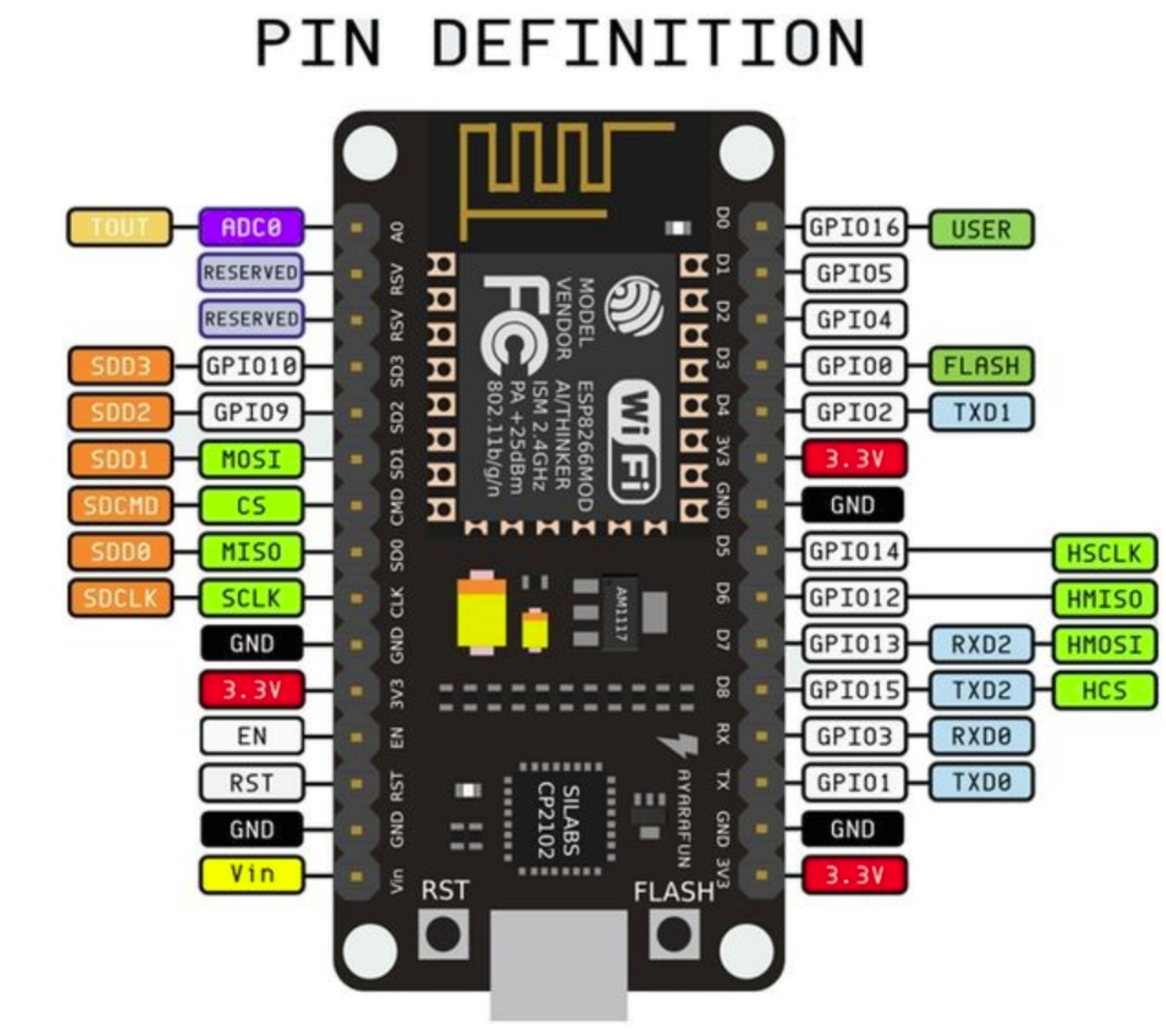
IO~~~는 우리가 임의로 설정 가능한거라 아무데나 연결하면 됨!
LED의 긴쪽이랑 저항
짧은게 그라운드랑
팩트 : 짧은쪽이 저항
FTDI232 여기서 가운데랑 3.3V를 연결하기
VCC : +
파일 - 환경설정 - 추가적인 보드 매니저 URL : http://arduino.esp8266.com/stable/package_esp8266com_index.json 이거 입력하면 보드매니저에서 8266 검색 가능

그리고 보드를 node mcu 1.0 esp12 어쩌구로 하고 예제 basic blink
핀번호 맞춰야해 나는D7로해서 13으로 한거

코드
/*
  Blink

  Turns an LED on for one second, then off for one second, repeatedly.

  Most Arduinos have an on-board LED you can control. On the UNO, MEGA and ZERO
  it is attached to digital pin 13, on MKR1000 on pin 6. LED_BUILTIN is set to
  the correct LED pin independent of which board is used.
  If you want to know what pin the on-board LED is connected to on your Arduino
  model, check the Technical Specs of your board at:
  https://www.arduino.cc/en/Main/Products

  modified 8 May 2014
  by Scott Fitzgerald
  modified 2 Sep 2016
  by Arturo Guadalupi
  modified 8 Sep 2016
  by Colby Newman

  This example code is in the public domain.

  http://www.arduino.cc/en/Tutorial/Blink
*/

// the setup function runs once when you press reset or power the board
void setup() {
  // initialize digital pin LED_BUILTIN as an output.
  pinMode(13, OUTPUT);
}

// the loop function runs over and over again forever
void loop() {
  digitalWrite(13, HIGH);   // turn the LED on (HIGH is the voltage level)
  delay(1000);                       // wait for a second
  digitalWrite(13, LOW);    // turn the LED off by making the voltage LOW
  delay(1000);                       // wait for a second
}
참고 : http://www.hardcopyworld.com/gnuboard5/bbs/board.php?bo_table=tech_comm&wr_id=157
ESP8266 활용 가이드 - ESP8266 Arduino IDE 활용법 > Communication module | HardCopyWorld
ESP8266 활용 가이드 - ESP8266 Arduino IDE 활용법 > Communication module | HardCopyWorld
www.hardcopyworld.com
Fritzing
Fritzing is an open-source hardware initiative that makes electronics accessible as a creative material for anyone. We offer a software tool, a community website and services in the spirit of Processing and Arduino, fostering a creative ecosystem that allo
fritzing.org
ESP 12 unusable pins - Arduino Stack Exchange - https://arduino.stackexchange.com/questions/56383/esp-12-unusable-pins
ESP 12 unusable pins
The ESP 12 board has 22 pins Are all of them usable? I understand that there is an external flash memory that is accessed through SPI, but I'm not sure what the impact on the pins is. And if it...
arduino.stackexchange.com
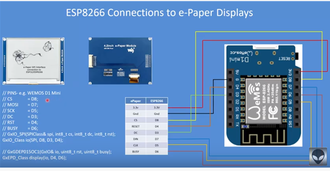
BUSY -> 4, RST -> 16, DC -> 17, CS -> SS(5), CLK -> SCK(18), DIN -> MOSI(23), GND -> GND, 3.3V -> 3.3V

ESP8266-WiFiWebServer-브라우저로 LED 제어하기 – 영엑스에프에프
ESP8266 보드를 사용하여 웹서버를 구축, 브라우저로 LED를 제어해 봅니다. 프로젝트를 진행하기 위해서 무선 공유기 2.4G가 필요합니다. 아두이노 개발환경 구축(아두이노가 설치되어 있으면 skip~) ESP8266-IoT 보드에 코드를 작성하고 작성한 코드를 업로드하는 프로그램을 설치해야 합니다. https://www.arduino.cc/en/Main/Software 로 이동하여 아래의 다운로드 영역을 찾습니다. 사용하고 계신 운영체제에 맞는 프로
www.0xff.co.kr
https://www.arduino.cc/en/Main/Software#/? : 아두이노 설치
[김민주] [오후 10:48] https://m.blog.naver.com/PostView.nhn?blogId=cosmosjs&logNo=221041074028&proxyReferer=https%3A%2F%2Fwww.google.com%2F
NodeMCU(ESP8266) 개발보드 사용하기(2) : 웹브라우저에서 LED 제어하기
앞서 LED를 켜고 끄는 예제를 만들어 보았다. 이제 본격적으로 wifi모듈을 사용하는 예제들을 시도해 보...
blog.naver.com
[김민주] [오후 10:46] https://deneb21.tistory.com/393
[아두이노] FTDI USB Serial 모듈과 아두이노 프로 미니 - FT232RL 칩 사용 보드
아두이노 프로 미니 보드와 같은 보드는 PC와의 시리얼 통신을 위한 칩이 없습니다. 아두이노 우노나 나노 같은 경우는 자체에 통신칩을 내장하고 있어서 바로 PC에 연결해서 프로그램의 업로드가 가능하지만 프로..
deneb21.tistory.com
[김민주] [오후 10:47] https://www.usb-drivers.org/ft232r-usb-uart-driver.html
FT232R USB UART Driver - USB Driver
The FT232R USB driver is a bit of a complicated install. The screenshots below will give you directi
www.usb-drivers.org
아두이노에서
툴 - 보드 : General ESP8266 Module
포트 : COM7
시리얼 모니터도 켜기
=====2019.7.21=====
http://raphuscucullatus.blogspot.com/2018/05/nodemcu-und-e-paper-display.html
Nodemcu und e-Paper-Display
e-Paper-Display sind eine interessante Sache, da sie das dargestellte Bild auch halten, wenn das Display nicht mehr über Strom versorgt wir...
raphuscucullatus.blogspot.com
gfx 설치
깃에서 다운로드
아두이노에서 zip 추가
GxEPD_Example 샘플 이거 불러와서
#include <GxGDEW0213Z16/GxGDEW0213Z16.h> // 2.13" b/w/r
주석 해제. 우리는 2.13 인치라 2.13 거를 주석 해제한 것!
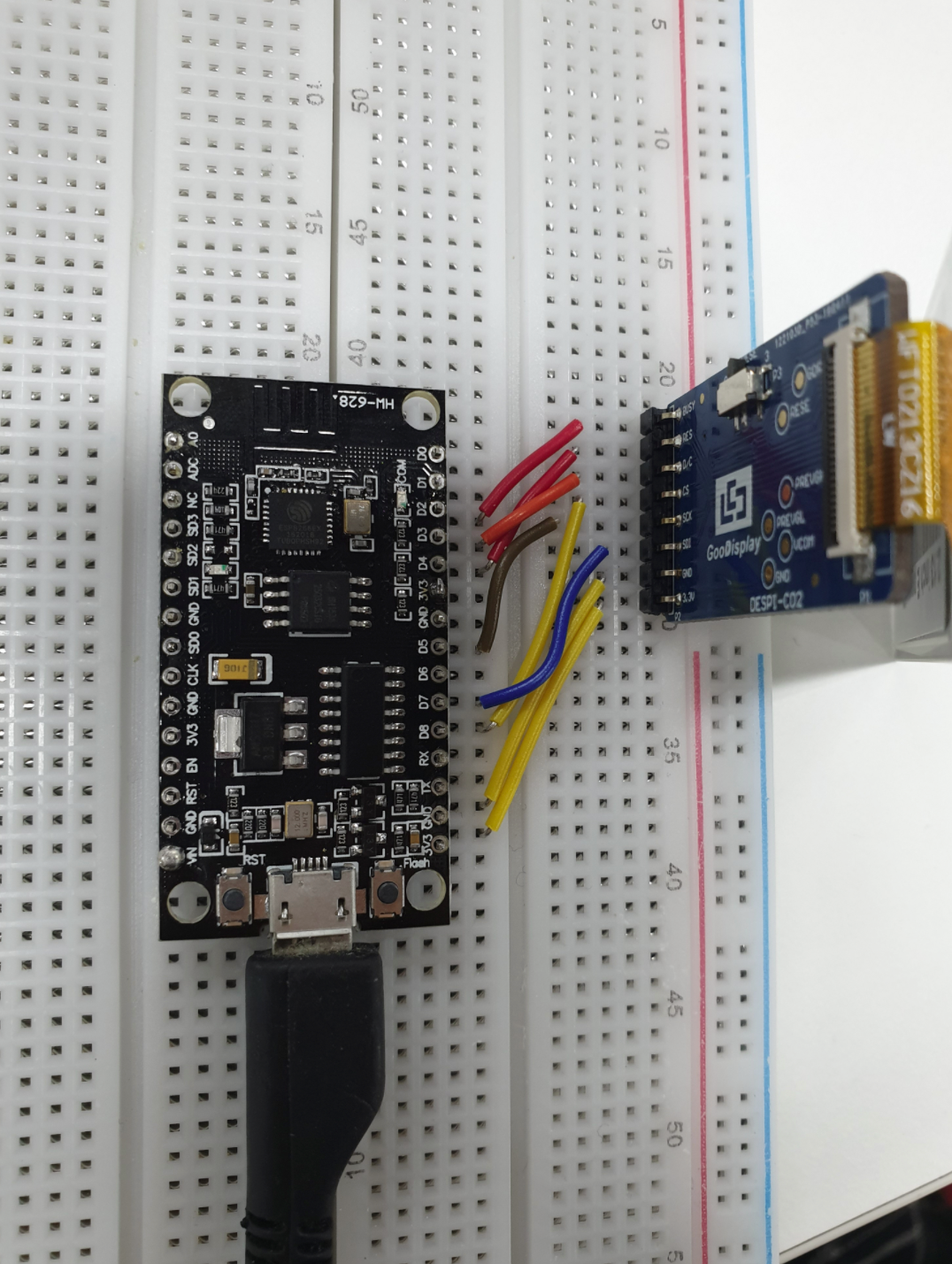
디스플레이(2.13inch e paper C) - NodeMCU
BUSY - D2
RST(RES) - D4
DC(D/C) - D3
CS - D8
CLK(SCK) - D5
DIN(SDI) - D7
GND -GND
3.3V - 3.3V
이렇게 연결!

포트는 블루투스 말고!
'Archive' 카테고리의 다른 글
| 2020년 개발 일지 (0) | 2020.03.05 |
|---|---|
| [Roubit] 개발일지 (2) | 2020.02.25 |
| [엔구 화상영어] close (not far) / Similar (0) | 2019.01.28 |
| [엔구 화상영어] ★we went sightseeing (0) | 2019.01.27 |
| [엔구 화상영어] The taxi driver does not go straight to the destination but turns around. (0) | 2019.01.27 |